
What Is a Subpanel, and When Does a Full Panel Need One?
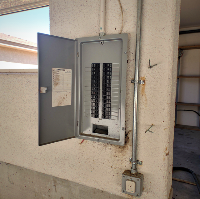
The panel door swings open and the story is right there on the directory card: every line filled in, two of them penciled over where circuits got renamed, and the word SPARE crossed out at the bottom. Behind the card, every position holds a breaker, a couple of them skinny tandems doubled into one slot. The circuit for your new workshop has nowhere to go.
A subpanel is a second breaker enclosure, fed by one set of conductors from the main panel, with its own bus and branch breakers. Whether you need one depends on which thing the panel ran out of: physical breaker positions, or amperage. Those are two separate failures with two separate fixes, and at the panel door they look identical.
Running Out of Breaker Positions Is a Question of Geometry
Inside the enclosure, the bus bars carry a fixed number of stab positions, set when the panel was manufactured. A 20-space panel has 20 places where a breaker can be seated, and its label states how many circuits it is rated to hold. A 120-volt circuit takes one position. Anything at 240 volts, whether a range, a dryer, a water heater, or a car charger, takes two adjacent positions so the breaker can bridge both legs of the bus. Four loads like that consume eight of your twenty places before a single lighting circuit is counted.
Tandem breakers fit two 120-volt circuits into the footprint of one position. But they seat only in the positions that the specific panel is listed to accept, and a panel can enforce that with rejection tabs on the bus that physically block a tandem from seating anywhere else. That is a fact about the panel on your wall, printed on its own label. A tandem also has no way to reach opposite bus legs, so it cannot serve a 240-volt load at all.
A Subpanel Divides the Amperage You Already Have
Every branch circuit in your house draws its current through the main breaker, whatever enclosure its breaker sits in. A circuit fed from a subpanel pulls through the subpanel bus, back along the feeder, through the feeder breaker, the main panel's bus, the main breaker, and out to the meter. A subpanel re-divides the amperage already arriving at the house; it does not add any.
Telling them apart takes arithmetic. An electrician runs a load calculation: the fixed loads, meaning the heating and cooling equipment and the large appliances, plus a lighting and receptacle allowance based on your floor area, with demand factors applied because those loads do not all run at once. The result is compared against your service rating, and a recording ammeter left on the service conductors for a week adds a measured peak to that estimate.
If that arithmetic lands at or above your service rating, more breaker positions change nothing: the new circuits would push total draw past what the service can carry. The question becomes the size of the service itself, which is a separate decision with its own arithmetic.
A Subpanel Is One Feeder and a Second Bus
A double-pole breaker is installed in the main panel, sized to the feeder it protects. Four conductors leave it: two ungrounded legs, one grounded neutral, and one equipment grounding conductor. They land in a second enclosure with its own bus, neutral bar, ground bar, and count of positions.
The feeder breaker occupies two positions in the main panel, so a subpanel spends two slots to gain eight, twelve, twenty, or more, depending on the enclosure you install. The subpanel also carries its own bus ampere rating, which the feeder breaker cannot exceed: a 100-amp-rated subpanel can be fed by a 60-amp breaker, while a 60-amp-rated one cannot be fed by a 100-amp breaker.
The service itself is untouched: one connection to the utility, one meter, one main disconnect over everything downstream.
Distance Turns Six Home Runs Into One Feeder
One case for a subpanel starts outside your house entirely: a detached garage or workshop sitting 80 to 150 feet away, needing lights, two or three receptacle circuits, a 240-volt outlet for a compressor or a welder, and a charger you may add later.
There are two ways to power that: a home run from the main panel for every circuit, or a single feeder split at the far end. Six home runs means six sets of conductors carried the full length, eight positions consumed in the main panel once the two 240-volt circuits are counted double, and a derating penalty on top. Conductors bundled in one raceway warm each other and cannot shed that heat the way a single run can, so the current each one is allowed to carry comes down as the count goes up. The ampacity adjustment tables electricians size from put that at 80 percent for four to six current-carrying conductors, and 70 percent at seven to nine. Three 120-volt circuits in one conduit already put six current-carrying conductors in it, so your wire gets larger to carry the same load.
Voltage drop is the real argument. It is current multiplied by conductor resistance, and resistance rises with length counted in both directions, out to the load and back. A 60-amp load on 6 AWG copper drops about 5.9 volts over a 100-foot one-way run, near 2.5 percent of 240 volts, and at 175 feet it passes 4 percent. The effect first appears in motors: an induction motor at reduced terminal voltage draws more current to produce the same torque, and that extra current turns into heat in the windings. Your shop lights dip when the compressor starts, and the compressor runs hotter than it should.
One feeder settles that calculation once, for the whole building's diversified load, on one set of conductors you can upsize without multiplying the work. The branch circuits inside the far building are then 10 to 30 feet long, and their drop is negligible.
In a Subpanel, the Neutrals and the Grounds Stay Apart
A main panel and a subpanel look alike inside, and they are bonded in opposite ways. At the service equipment, the grounded conductor (the neutral) and the equipment grounding system are bonded at a single point by a bonding screw or strap. In a subpanel, that bond is deliberately left out. The neutral bar is isolated from the enclosure on insulating standoffs, and the grounding conductors terminate on a separate bar screwed directly to the metal enclosure.
Return current takes every path available back to its source, dividing among those paths in inverse proportion to their resistance. Bond the neutral bar to the can at your subpanel, and the neutral conductor and the equipment grounding conductor are joined at both ends, forming two parallel paths for the same return current. Ordinary load current then splits between them: part on the neutral, part on the grounding conductor, the metal conduit, the enclosure, and any metal piping bonded to that system. This happens whenever the circuit is loaded, during completely normal operation.
Metal parts that normally sit at earth potential are carrying current, and current through any resistance produces a voltage, so they sit slightly above earth. The fault-clearing path is loaded continuously, so a conductor sized for the fraction of a second it takes a breaker to open is instead warming under load all day. And nothing is held in reserve: if one neutral connection loosens, the return current takes whatever path is left, and the whole return for those circuits lands on the grounding conductor.
TIP: In a correctly wired subpanel, the neutral bar sits on insulated mounts with its bonding screw or strap removed, while the ground bar is fastened to the can. An electrician can confirm both with the cover off.
A detached building adds one more piece: the feeder carries an equipment grounding conductor back to the main panel, and the building also gets its own grounding electrode, such as driven rods. That electrode gives the structure an earth reference and a path for lightning energy. It does no fault clearing: soil resistance is far too high, and a 25-ohm electrode at 120 volts passes under 5 amps, which will never open a 20-amp breaker. Fault current gets home on the equipment grounding conductor. Which of these details an inspector checks and what has to be permitted before any of it starts belong to the authority having jurisdiction where you live.
Frequently Asked Questions
Not all of them do. Subpanels are sold main-lug-only, where the feeder lands directly on the bus, and the feeder breaker is the only overcurrent device ahead of it, or with a main breaker built into the enclosure. The main-breaker version provides a disconnect at the subpanel itself, which lets you shut off power to a detached workshop without walking back to the house.
The feeder breaker sets it, and the weakest-rated point in the path sets the limit, so a conductor good for more heat is still held to what its terminations are marked for. Where your breaker and its lugs both read 75C, the pairing comes out of the 75-degree column of the ampacity tables: a 60-amp feeder takes 6 AWG copper or 4 AWG aluminum, both rated 65 amps there, and a 100-amp feeder takes 3 AWG copper or 1 AWG aluminum. Longer runs get sized up from there.
That is the situation a subpanel exists for. The feed goes underground, either as individual conductors pulled through PVC conduit or as a listed direct-burial cable, and it terminates in a subpanel mounted inside your garage. Trench depth changes with the wiring method and with what the run passes beneath, such as a driveway, and the depth held to on site is set by the authority having jurisdiction.
Yes, in an enclosure rated for it. An indoor panel is a NEMA 1 can, and its seams and knockouts do nothing about water. An outdoor subpanel is NEMA 3R, rain-tight, with conduit entries at the bottom and a small weep opening at the low point to allow condensation inside to drain out. Put a NEMA 1 enclosure on your exterior wall, and you are putting water on the bus.
Yes, at feeder sizes. Large aluminum feeder conductors and the small aluminum branch-circuit wiring found in some older homes are two different materials handled two different ways. The connection is what matters: terminals listed for aluminum and marked AL9CU or CU/AL, an oxide-inhibiting compound on the stripped conductor, and the torque value printed on the enclosure label applied with a torque tool. Aluminum expands and contracts more than copper, so an under-torqued lug on your feeder loosens with heating cycles and then heats further.
The manufacturer's label inside your panel door lists the panelboard's amperage rating, which is separate from the main breaker installed in it. A 200-amp-rated enclosure holding a 125-amp main is a 125-amp service today, and the enclosure rating is what a larger main would later have to fit within. A 100-amp-rated enclosure is finished at 100 amps, whatever breaker goes into it.
A load calculation and the numbers on the panel label settle the space-or-capacity question before any conductor gets bought — subpanels, detached-building feeders, and panel and service upgrades all start from the same reading. Efficient Electric serves Phoenix, Peoria, and the surrounding West Valley. Call (623) 810-9905.